 will stedden
Bluetooth controlled Redbot construction
For part of the Ray elementary after school electronics and robotics club (R-ASER), I'm prototyping a robot that can be remotely controlled via a serial connection through bluetooth. The following is the rough draft of the classroom instructions. (PS, volunteering with kids is fun so go out and do it.)
Adding the Bluetooth module
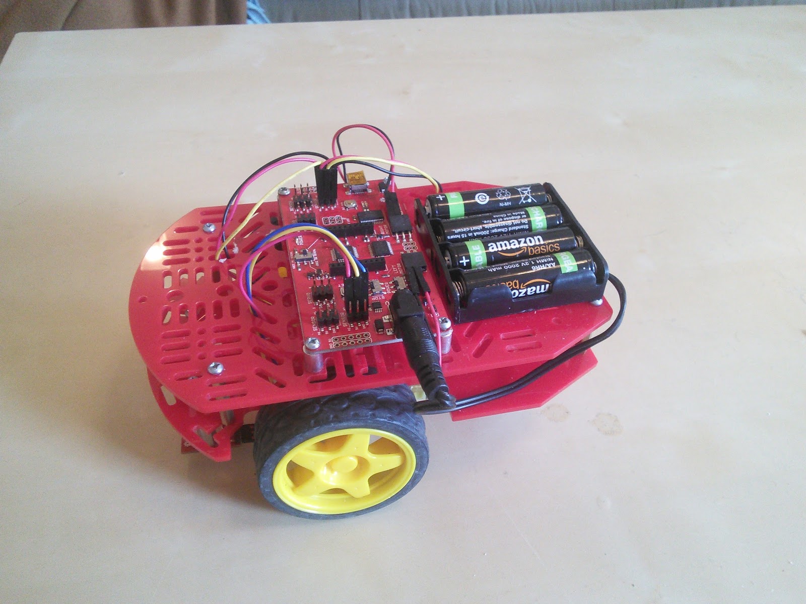
This lesson starts with a fully assembled and functional Redbot chassis. You can find more info abut the robot kit and instructions on sparkfun's tutorial website, and you can see more of our Redbot based projects once we have them online. This is what our original Redbot looks like before we start construction.
We'll be modifying this basic robot with an a bluetooth module that doesn't come from sparkfun so we'll get all the excitement of working with non-kit electronics. We're going to be adding an HC-05 BT module like the one pictured below.
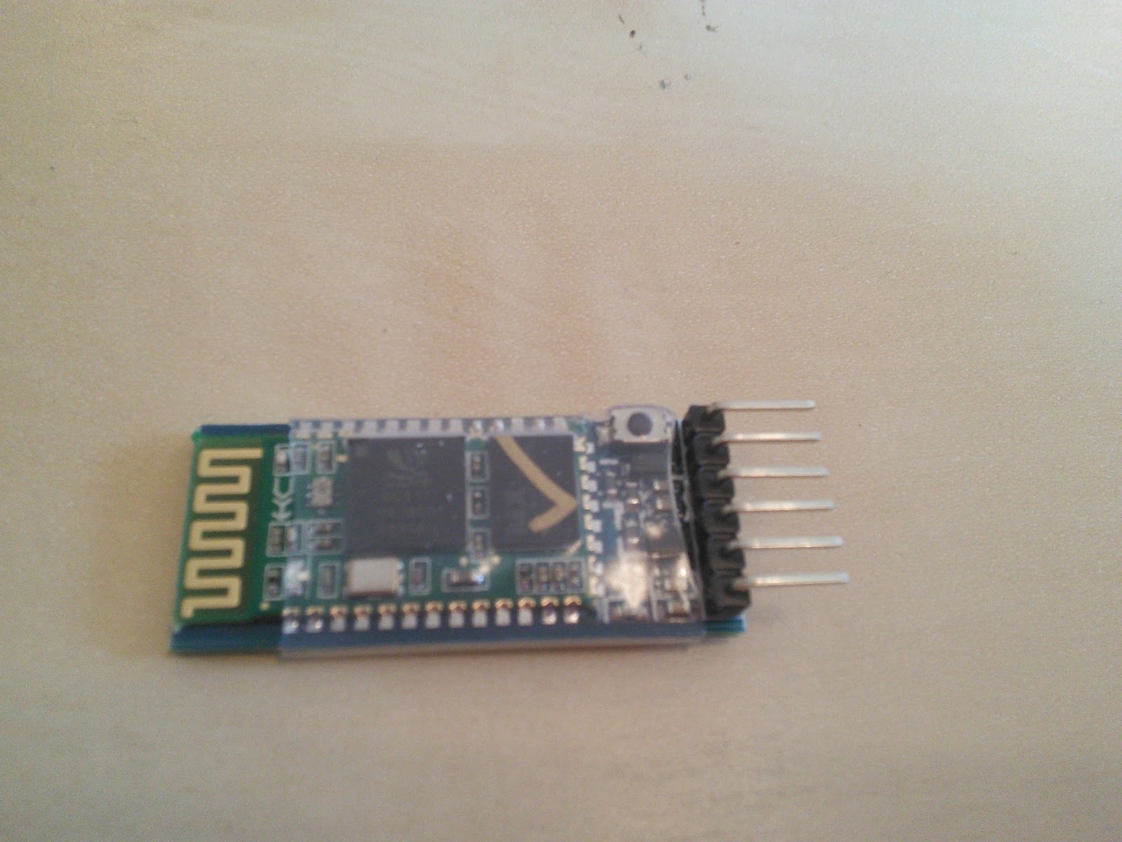
This device contains a fully functional bluetooth transmitter and receiver so we don't have to worry about building the parts that transmit data through the air. That means all we will have to do is listen to the serial data coming from the device as if it were coming from the USB cable.
Connecting through a voltage divider
The big trick with this device is that it communicates using only 3.3 V while the Arduino usually uses 5 V. This means that if we send information to the using 5V we will overload the circuit and burn the chip up. This cause us to need to use a voltage divider to decrease the voltage going to the bluetooth module. We'll put together a circuit based on this excellent Instructable from techbitar

To start we'll connect black, red, yellow, and green wires to the bluetooth module like in the image.
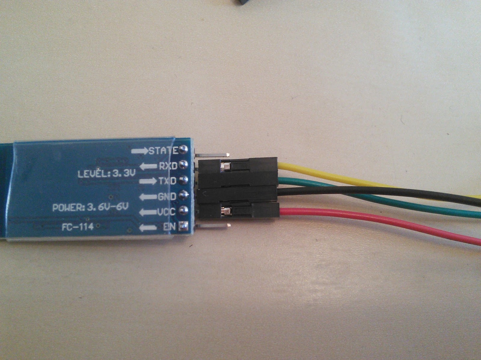
The black and red wires will just connect the bluetooth module to the power and ground of the Arduino microcontroller. The yellow and green wires will connect to analog ports on the Arduino in order to transmit and receive signals. Serial signals work by having each connected device transmit information from a port labeled TXD and receive signal from a port labeled RXD. So we're going to use the green wires to receive signals from the Arduino (RXD) to the bluetooth module, and we're going to use the yellow wires to transmit signals to the Arduino (TXD).
The voltage divider
The signal that is going into the bluetooth module needs to be at 3.3v so we will need to connect that wire through a voltage divider. A voltage divider just causes some voltage to be lost directly to ground without going through another part of the circuit.

In our circuit that means we need to add two resistors connected to the yellow lead coming out of the RXD pin.

We'll use a 1 kOhm resistor on the line to the Arduino input and a 2 kOhm resistor on the line to the ground. This will cause most of the voltage to be on the Arduino input with only a little being divided away. What would happen if we had used 2kOhm on both?
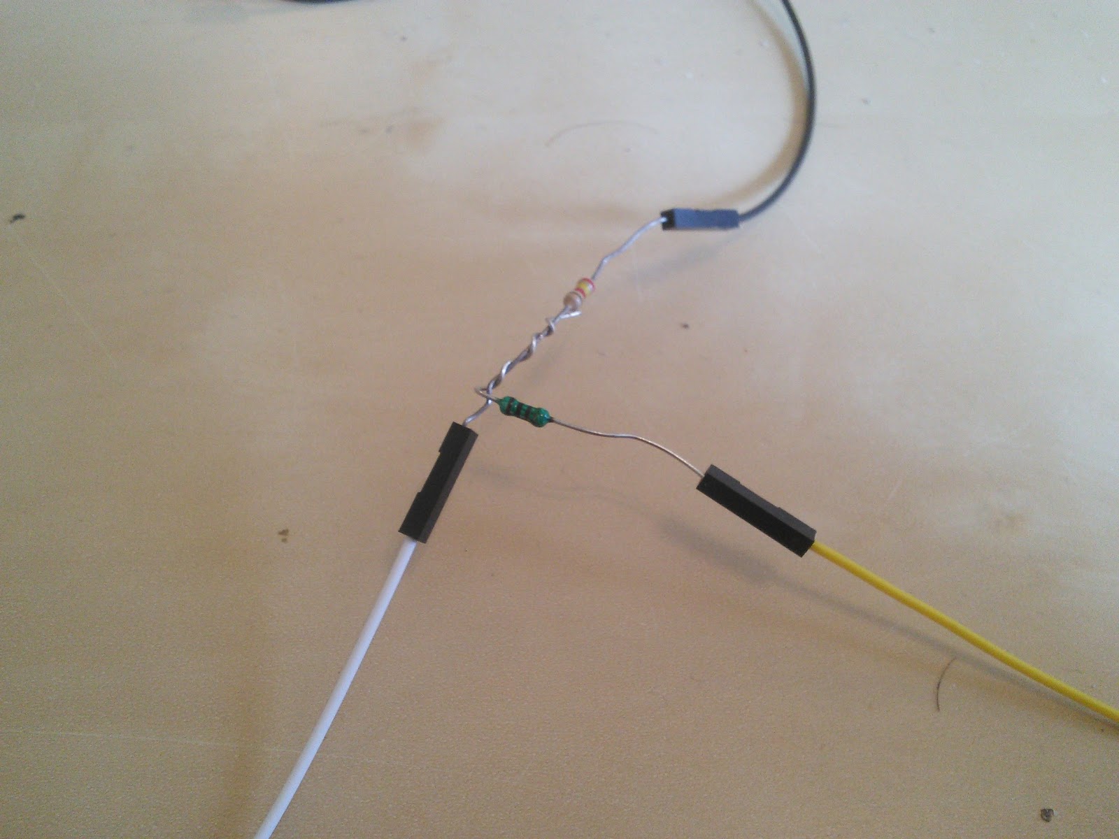
To make things more clear I used a black wire coming off the 2 kOhm resistor (going to ground) and a white wire off the 1 kOhm resistor (going to the inputs).
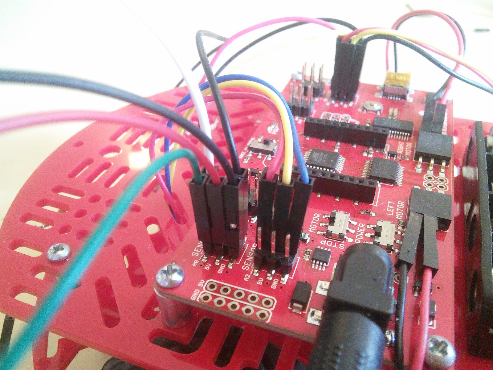
Connecting to the board
The final step for connecting the module is to plug it into the board itself. You can figure out how to connect our wires from the diagram above and using your logic. The important thing to know is that A0 is going to be doing the receiving from the bluetooth module while A1 is going to be doing the sending to the module. Can you figure out which color wires should connect even without looking? IMPORTANT: Two of the wires in the next image are reversed so you have to figure out which color goes where!
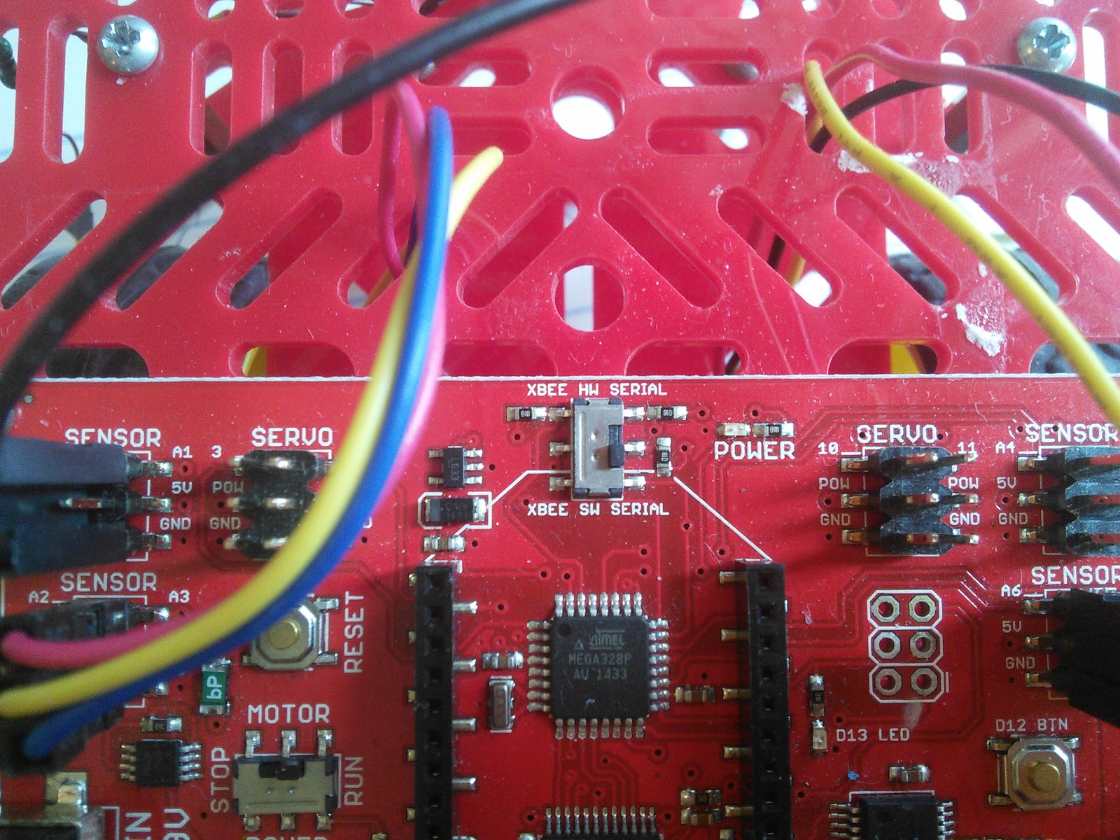
The board has a switch that you'll have to change too. This switch changes the Arduino circuitry so that now analog ports A0 and A1 will work just like the Serial USB works. This is called SoftwareSerial and we'll talk more about it next time, but for now just make sure that the switch points to "XBEE SW SERIAL".
Renaming the Bluetooth Module
If you are working with more than one bluetooth module in the same area, you will need to rename your module so that you don't get it confused with any of the other ones in the area. To do this you will need to upload some special code to your Arduino that'll let you write from your USB serial to the modules serial line.
#include <RedBot.h>
#include <RedBotSoftwareSerial.h>

RedBotSoftwareSerial swsp;

void setup() {
  Serial.begin(9600);
  Serial.println("Arduino is ready");
  swsp.begin(9600);
  Serial.println("BTserial started at 9600");
  delay(50);
}

void loop() {
  if (swsp.available())
    Serial.write(swsp.read());

  // Keep reading from Arduino Serial Monitor and send to HC-05
  if (Serial.available()){
    char c = Serial.read();
    Serial.write(c);
    swsp.write(c);
  }
}
After this code is uploaded you should power on the bluetooth module. Next open the Serial Monitor and you should see the text "Arduino is ready" and "BTSerial started at 9600". At this point, if you type in the Serial Monitor nothing special should happen. You need to activate the module's AT mode, which will allow you to change internal programming of the module. To do this you need to press and hold the tiny button sitting next to the EN line on the module.
IMPORTANT: In the bottom right of the Serial Monitor, you need to make sure you have selected "Both NL and CR" and "9600". This ensures that every time you press enter, the message is sent with a New Line character. The Bluetooth module requires new lines at the end of every command.
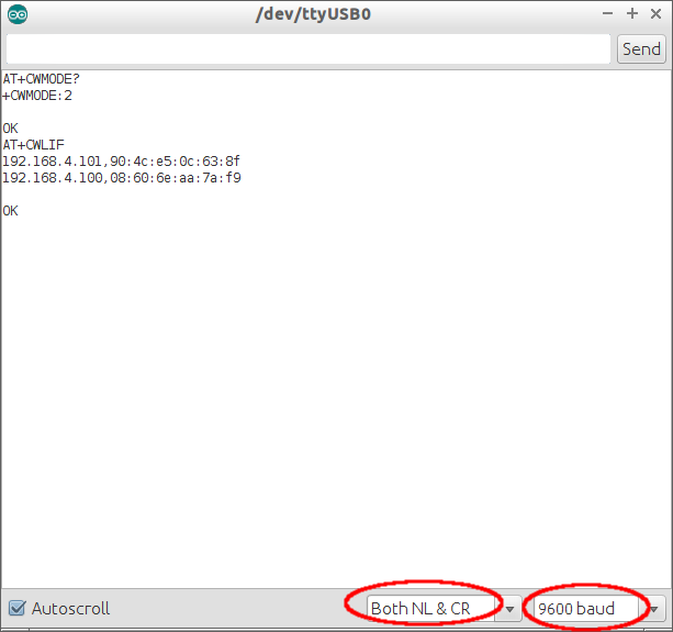
While holding down that button you can type "AT" and the serial monitor should respond "OK." Next type "AT+NAME" to see the current name of the module(which should be "HC-05"). Finally type "AT+NAME=####" where you should put a unique name in place of #### so that you can identify your module when you try to pair with it. After you've done that, simply turn the Arduino back off and back on to reset the Bluetooth module.
Connect bluetooth device
Again connecting will be different on every machine, but we'll show the steps for Windows.
You'll start by making sure that the bluetooth module is powered on and blinking. Next, right click on the little bluetooth icon in the corner and select "Connect Devices" or something similar. This will open a dialog that let's you search for the bluetooth module. There's no guarantee on the name but it might say HC-05 if you're lucky.

You'll have to move through a few more steps until you need to add a pairing code to make the devices talk to each other. This is just how bluetooth makes sure that you aren't accidentally connecting to the wrong device. For me the pairing code was 1234, but this is not guaranteed to be correct.

You'll have to figure out which serial port the device is talking to. That can be found in the device properties.

Write to Serial Bluetooth with Tera Term
Next, we have to set up Tera Term to talk to that port. Tera Term is pretty much the same thing as the Serial Monitor, but it works slightly better. Importantly, we can use it with the COM port that the Bluetooth is talking to.
Install Tera Term
The first thing we're going to do is get Tera Term onto our machines. Installing Tera Term will be different on every system, but for Windows machines, you can simply download the latest .exe file from their website.
https://en.osdn.jp/projects/ttssh2/releases/
Once Tera Term is installed, open it. After you open Tera Term you just have to select he same COM Port connected to the Bluetooth. The trick here is that our Bluetooth modules actually connect to two COM Ports, but only one of them works. It appears to be totally random which COM port is selected so you have to guess. If you guess correctly, the blinking pattern on the Bluetooth chip will change to two short flashes. If you guess wrong, you just have to reopen Tera Term and select the other port.

Once you think you're connected you need to get some code on your Arduino to really see if it's working.
Checking for connectivity
As a simple test case we can use the following code from techbitar to blink code over the serial port once we have the computer connected to the Arduino.
#include <RedBot.h>
#include <RedBotSoftwareSerial.h>

int counter =0;
RedBotSoftwareSerial swsp;

void setup() {
  swsp.begin(9600);
  delay(50);
}

void loop() {
  counter++;
  swsp.print("Arduino counter: ");
  swsp.println(counter);
  delay(500); // wait half a sec
}
The part where we define swsp relies on using Software serial to make a "software" version of the regular serial port (i.e. the one we use when we write Serial.println()). We don't have to worry about how this works under the hood (unless something doesn't work).
Challenge: Drive the car
You now have swsp working just like a regular USB serial port. So use it just like you would to control the Redbot! If you can't figure it out, you can cheat and click in the box to see the code to drive the car.