 will stedden
RASER Week 6: Arduino LED Passcode Pad - Part 2
Two weeks ago, we started learning about one of the most important things Arduinos can do: read input voltages. We want to continue working on reading input this week and connect our input back to output LEDs.
Feeling Voltage with a Van de Graaff Generator
To get started on today's lesson, we want to make the point of what a voltage actually is. A great way to that is to literally feel the voltage using a Van de Graaff generator.
A Van de Graaff generator is a device that builds up large amount of static electricity that can be transmitted to another person when she touches it. The build up of electricity produces a voltage difference between the person becoming charged and the rest of the Earth (called the ground).
Now even if the person lets go of the generator, she still has that voltage potential built up in her. We can even measure the voltage difference using a multimeter if the voltage isn't too high.
When the person then touches the ground, the voltage difference produces a current that generates a spark. The voltage is dissipated very quickly so the shock only lasts an instant. After that, the person has returned to the same voltage as ground.
This is something important to learn about circuits: just because a circuit element isn't directly connected to the plus end of the battery, doesn't mean that it might not have a voltage built up on it. In order to make sure a part of the circuit is at 0 voltage, you have to connect that part of the circuit back to ground.
Using a Button To Turn on an LED
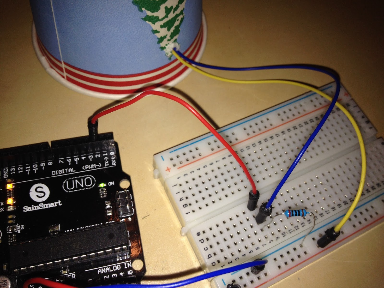
Next we want to continue our work with Arduino Serial Input from last week. Start by rebuilding the basic input button.
When that's done we can start adding to the code to use the input voltage on pin 2 to control the output voltage on pin 13. Try modifying the code to look like this:
int pushButton = 2;
int led = 13;


void setup() {
  Serial.begin(9600);
  pinMode(pushButton, INPUT);
  pinMode(led, OUTPUT);

}

void loop() {
  int buttonState = digitalRead(pushButton);
  digitalWrite(led1,buttonState);
  Serial.println(buttonState);
  delay(1);
}
The red lines in this code are used to control the LED. The first two parts are just like from the LED Blink program. The last line performs a digitalWrite using the state of the button that we read in from digitalRead. This makes it so that the LED will only light up when the button is pushed.
To make this work, we just need to add an LED to pin 13 like we did back in the LED Blink Program from Week 3.

And whenevever we push the button down we should see the LED light up. Give it a try. Remember that we aren't controlling the LED's voltage directly. We're controlling the Arduino, and the Arduino is controlling the LED.
Hooking up multiple LED Buttons
To really take advantage of the Arduino's inputs, we can hook up multiple LEDs and have them interact with our button in different ways.
As a simple example, try making the following changes to your code.
// digital pin 2 has a pushbutton attached to it. Give it a name:
int pushButton = 2;
int led1 = 13;
int led2 = 12;

// the setup routine runs once when you press reset:
void setup() {
  // initialize serial communication at 9600 bits per second:
  Serial.begin(9600);
  // make the pushbutton's pin an input:
  pinMode(pushButton, INPUT);
  pinMode(led1, OUTPUT);
  pinMode(led2, OUTPUT);
}

// the loop routine runs over and over again forever:
void loop() {
  // read the input pin:
  int buttonState = digitalRead(pushButton);
  // print out the state of the button:
  digitalWrite(led1,buttonState);
  digitalWrite(led2,1-buttonState);
  Serial.println(buttonState);
  delay(1);        // delay in between reads for stability
}
This will cause the two buttons to perform the opposite actions. The line
digitalWrite(led2,1-buttonState);will print the opposite of the buttonState (1-buttonState) to led2.
Next we just have to hook up another LED to pin 12. If you use red and green LEDs, this will result in a red light-green light, like a traffic signal.
You can also try messing around with delays to change how each LEDs are controlled. Experiment a little to see what you can do to control the LEDs differently.
The button triggered blink attack!
// digital pin 2 has a pushbutton attached to it. Give it a name:
int pushButton = 2;
int led1 = 13;
int led2 = 12;

// the setup routine runs once when you press reset:
void setup() {
  // initialize serial communication at 9600 bits per second:
  Serial.begin(9600);
  // make the pushbutton's pin an input:
  pinMode(pushButton, INPUT);
  pinMode(led1, OUTPUT);
  pinMode(led2, OUTPUT);
}

// the loop routine runs over and over again forever:
void loop() {
  // read the input pin:
  int buttonState = digitalRead(pushButton);
  //if the buttonState is 1, make the LEDs blink 4 times
  if(buttonState==1){
    digitalWrite(led1,HIGH);
    digitalWrite(led2,HIGH);
    delay(500);
    digitalWrite(led1,LOW);
    digitalWrite(led2,LOW);
    delay(500);
    digitalWrite(led1,HIGH);
    digitalWrite(led2,HIGH);
    delay(500);
    digitalWrite(led1,LOW);
    digitalWrite(led2,LOW);
    delay(500);
    digitalWrite(led1,HIGH);
    digitalWrite(led2,HIGH);
    delay(500);
    digitalWrite(led1,LOW);
    digitalWrite(led2,LOW);
    delay(500);
    digitalWrite(led1,HIGH);
    digitalWrite(led2,HIGH);
    delay(500);
    digitalWrite(led1,LOW);
    digitalWrite(led2,LOW);
    delay(500);
  }

  Serial.println(buttonState);
  delay(1);        // delay in between reads for stability
}
This block of code introduces the IF statement. The if statement asks a question, if(buttonState==1). IF the answer is true, the Arduino runs the code inside the brackets { ...}. If the answer to the question isn't true, the Arduino skips that code.
So when the button is pushed, we know that the buttonState==1 (buttonState is equal to 1). This means that the LEDs will then toggle from low to high over and over again, like it says to in the code.
At this point the LED is starting to listen to us and perform different tasks based on our input. This is really the first step towards unlocking all the amazing things an Arduino can do!
Challenge: Build the Passcode Game
I used combinations of input and output skills to build the Passcode Game that I showed last week. Now I challenge you to make one work! If you want a little help trying to put it together, you can look up the code and a schematic for the game on my GitHub page. If you're feeling up for a challenge try to build it yourself from scratch using some of the tools we learned about today.